
 Amplify Me
This is a small throughhole low voltage audio amplifier kit that is great for hobby level projects, instruments, and radios!
The LM386 is a low voltage audio amplifier that is great for hobby-level projects, instruments and radios!
Kit Parts
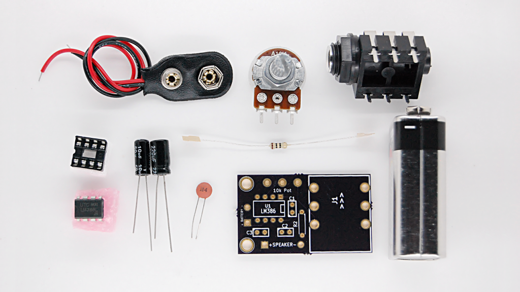
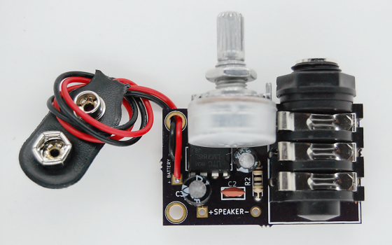
- PCB with mounting holes for battery and speaker
- LM386 Chip + 8 pin DIP Socket
- 10k potentiometer
- C1: 10uF
- C2: 0.1uF
- C3: 220uF
- R2: 10 ohms
- J1: 1/4″ female jack
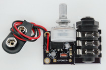
- 9v battery + battery clip
- LM386 Chip + Socket: You can choose to use the socket or not. The chip socket allows you to replace the LM386 chip if it ever malfunctions. However, use of the socket will not allow you to flush mount the potentiometer.
- 10k potentiometer: This is a volume knob! There are two ways to mount this. You can either solder wires to the three leads of the potentiometer and then solder those wires to the board, or, you can directly solder the potentiometer leads to the board. Remember, if you use the chip socket, you won’t be able to do the latter. The potentiometer control dial must be facing AWAY from the board.
- Speaker: This board ideally drives an 8 ohm impedance speaker. Wire holes have been provided. The speaker, however, has not. You could theoretically wire up a 1/4″ jack to this side and pipe it into a speaker or another amplifier.
- Battery: This board runs off of a 9v battery and holes have been provided for a battery clip!
- C1 (10uF): This is an optional capacitor that will increase the gain of the board from 20 to 200. The cathode (- stripe on the capacitor) faces down towards pin 8.
- C2 (0.1uF): The polarity of this capacitor doesn’t matter according to the datasheet so solder away!
- C3 (220uF): The cathode (- stripe on the capacitor) faces the right hand side. I’ve actually had fine luck with the cathode facing the left hand side, but, according to the datasheet, right hand side (towards the speaker) seems to be what you should do.
- R2 (10 ohms): No need to worry about polarity, just solder it in!
- J1 (1/4″ female jack): The jack’s input hole is up - as per the ^ arrows I’ve provided. This is so that if you decide to solder the potentiometer and jack up, you can mount it on a flat surface and they’d face the same direction. I would solder this one last. Also, the tip and ring are electrically connected, so stereo plugs (TRS) are unnecessary.
In our own Tymkrs projects, we’ve used this amplifier for cigar box guitars, electric guitars, and microphones as a second amplification stage. It’s handy to have around instead of having to breadboard up a version all of the time!
Youtube video showing what it sounds like:
Example Project:
