 VU Meter Me
This is a volume unit (VU) meter which helps you visualize your music and audio projects in the shape of a mini speedometer.
VU Meters are a great way to visualize your music and audio projects - so we decided to make one! After all, who doesn’t like blinking lights that react to music :) !
Kit Parts:
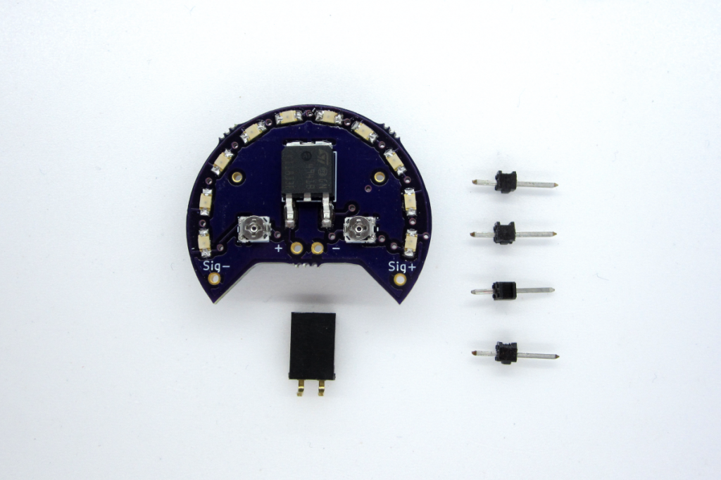
- Populated PCB with solder points for power and your audio signal
- 1x 1×2 right angle female header
- 4x 1×1 male header pins
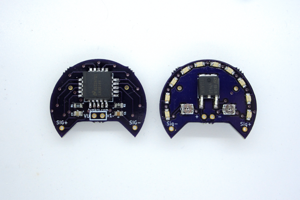
- + and -: + and - in the middle of the board is for your power supply - it powers the led bar driver chip and provides a reference for the audio signal. This board has a 5v LDO regulator which can handle a max of 30V (but I’d obviously recommend putting much less voltage into it).
- SIG + and SIG -: This is where you can solder/connect your audio signal to. SIG + can be used with your tip or ring, and SIG - would be your shield or ground.
- 1×2 right angle female header: This will be provided for the +/- power solder points. It can be soldered to come out under or over the board, or not soldered at all!
- 1×1 male header pins: Two of them can be used to solder into the SIG + and SIG - solder points. The other two can be soldered into the mounting holes for structural support. Those are not tied into the circuit. All header pins are breadboard friendly and thus can be easily put into a breadboard.
- Calibration w/ potentiometers: There are 2 trimmer pots that you can use to calibrate how much volume you want reflected in your VU meter. The circuit isn’t really hurt by experimentation with these, so with a screwdriver, you can easily change the look of the LEDs.
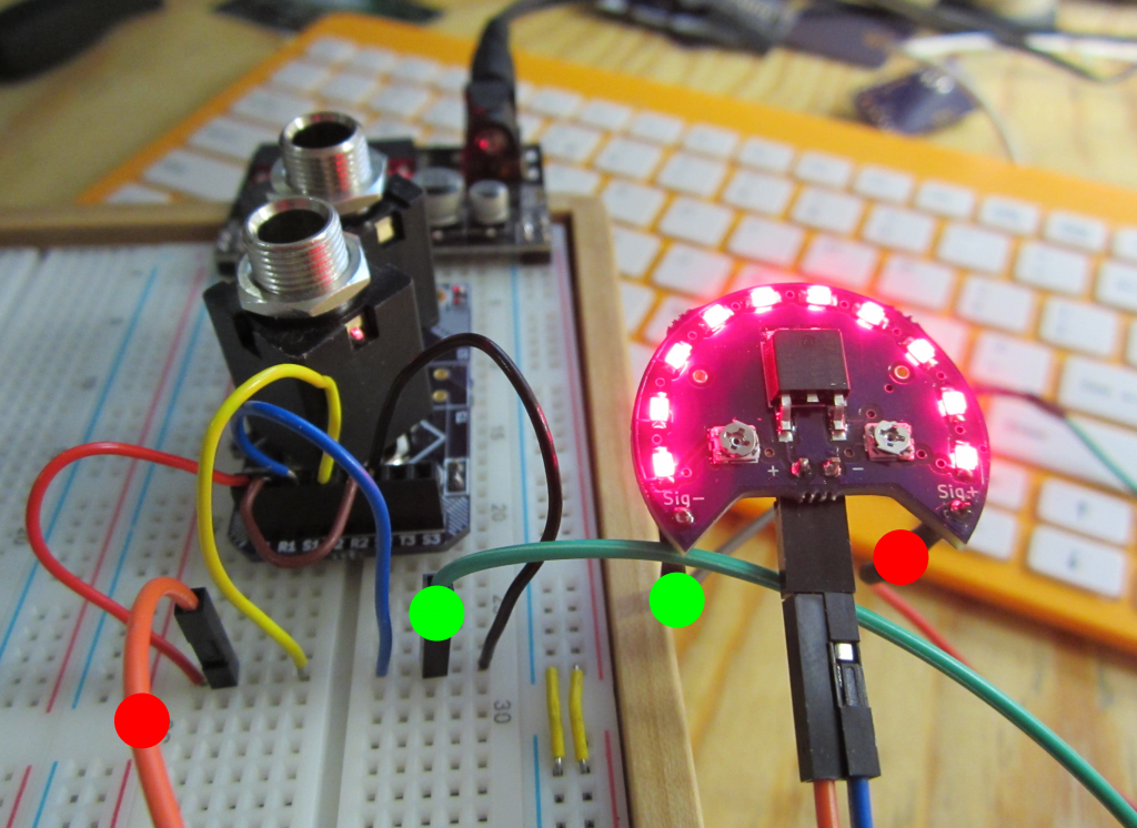
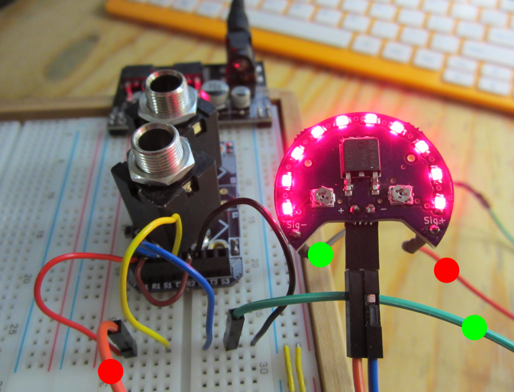
We have used this with audio from a gameboy and audio from a computer - both line level outputs. It should also work with headphone level output. In this example, we’ve used a Jack Me (1/4″ jack breakout board) as the source of our audio. We wanted to connect both jacks together in the Jack Me so that we could also hear the audio while the VU meter was playing.
The Jack Me allows you to take 2 1/4″ jacks and access the tip/ring/shield of your audio cable. For the VU meter - I took the tips of both jacks, connected them, and the signal from that went to the SIG + side of the VU board (as evidenced by the red dots).
The rings of both jacks were connected to each other by the brown wire. The shields of the jacks were connected together and the signal from that was directed to SIG - (as evidenced by the green dots).
And then using a Tautic breadboard power supply, I connected power up to the center of the VU meter board.